Made Noise – Sketch 7 (A Multimod Experiment)

I’ve had a full Make Noise synth for a while. In fact, I had far more Make Noise modules than I had space for, and with the recent release of Multimod, their new modulation tool, I decided to spring for a second 4-Zone CV Bus Case to avoid having to constantly rearrange the case from patch to patch. Multimod is an interesting tool. Billed as an eight output buffered multiple with several tricks up its sleeve, it presents a new method of spreading modulation signals around a case. It uses phasing, time, and speed manipulation in order to conjure this newfound magic. Fugue-like sequences can be created, as can wild modulation schemes, and many other things besides, all created from a single input signal. Being a Make Noise fan, I ordered one knowing only that it was a modulation source. If Make Noise has a gap in their lineup, it’s modulation sources. Once I saw the initial demo videos by Sarah Belle Reid and Red Means Recording, I ordered a second.

Although upon receiving them I used the new Multimods briefly to get an idea of how they worked, I hadn’t yet delved into what they can really do. I roughly recreated a couple of patches found in the videos, such as sending a sequence to several oscillators, and even trying it as a multitap, pitch shifting delay, but these were surface level primers, not any sort of real exploration. Being that Multimod presents a very new way of sending modulation around a synth, I was unsure how I might want to use them. My initial thought in ordering two was to use one for CV manipulation, and the second as an audio processor. I’ll certainly do more of that in the future, but I wanted to see if I couldn’t tackle an issue I noticed right away.

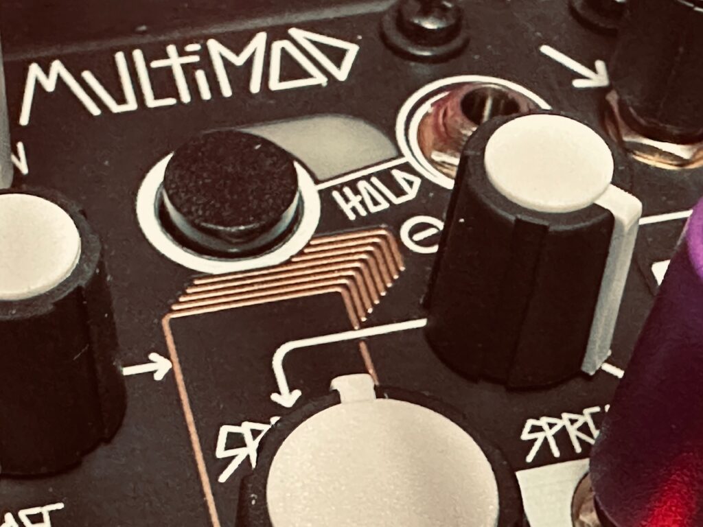
One of the highlights of the video demonstrations were the creation of fugue-like sequences, where many oscillators would receive the same sequence, but at different speeds or phased in time in interesting ways. But I also noticed immediately that although the sequence pitch data was spread around, there wasn’t a good way of spreading around an accompanying gate sequence for articulation. Some attempts at remedying this conundrum that I’ve seen involve using a separate gate sequencer, or even just a clock. And while deriving pitch and gate sequences independently is a particular strength of eurorack, that method seemed haphazard and insufficient for this application. I wanted more. I wanted the entire sequence at all of the outputs regardless of the speed or phase. So I thought about it, and suddenly a potential answer came to mind. Use one Multimod for processing the pitch sequence, and the other for processing the gate sequence. But there was still the problem of movement. I needed to move the knobs the exact same amount at the exact same time in order for the outputs on both modules to follow. How would I modulate them so that they were always doing the same thing at the same time and the gate sequences were following their pitch CV counterparts?
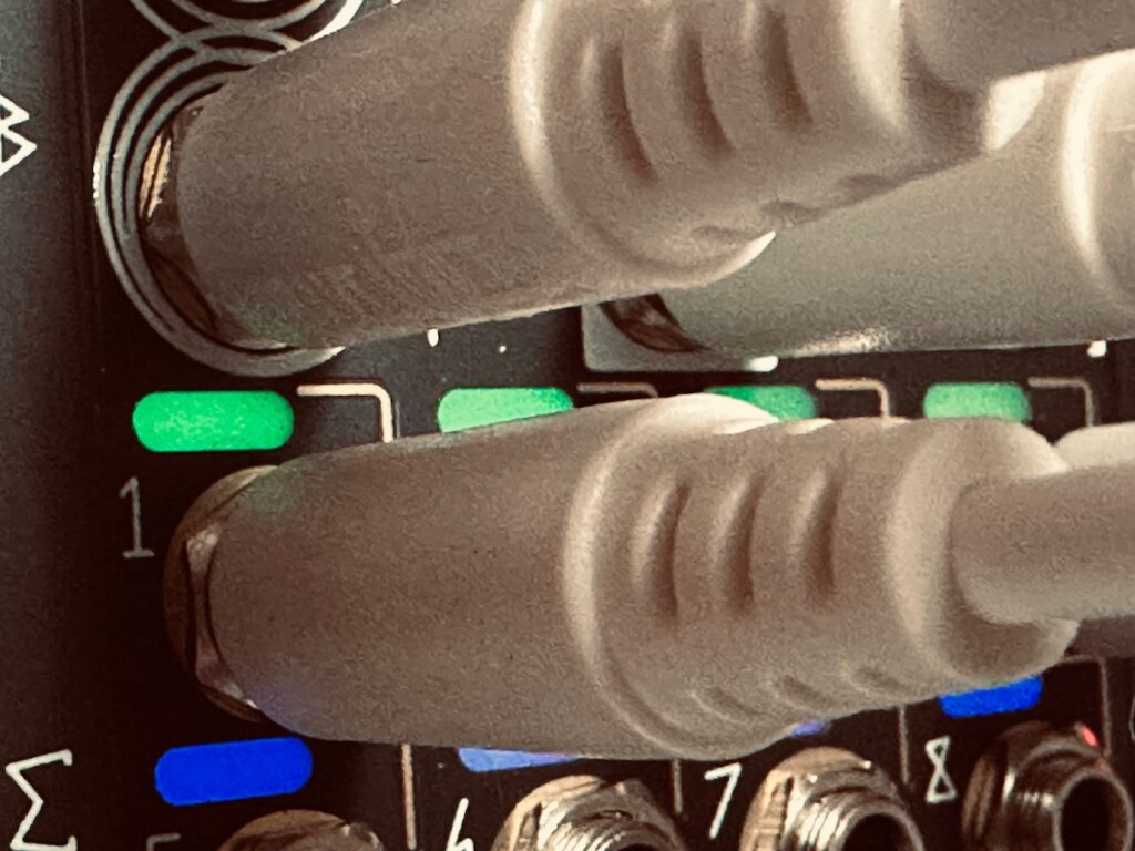
The CV Bus.

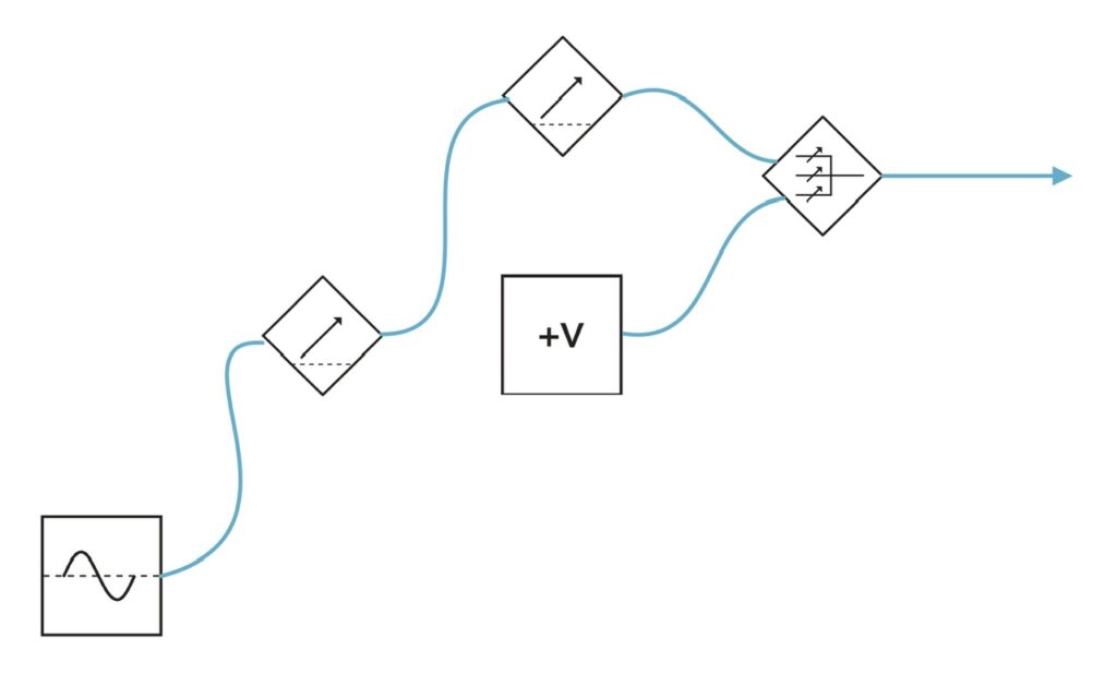
Although a Maths channel two or three could be used as an offset in the same way, I decided to use the CV outputs of the Noisy Fruits Lab Lemon, a very excellent standalone CV/MIDI controller, to manually control Multimod’s Time and Spread controls. My goals here were simple: to use two Multimod’s to control a single René CV and gate sequence, with the outputs on both being in sync with one another. If Multimod were an all analog module, I think this experiment would likely be dead in the water. I’m not convinced that parts and control tolerances would be close enough such that they would remain identical through modulation. But since Multimod is all digital, I surmised that so long as all of the Init settings were the same on both, they should (very theoretically) react the same to identical control voltage received at the same time.

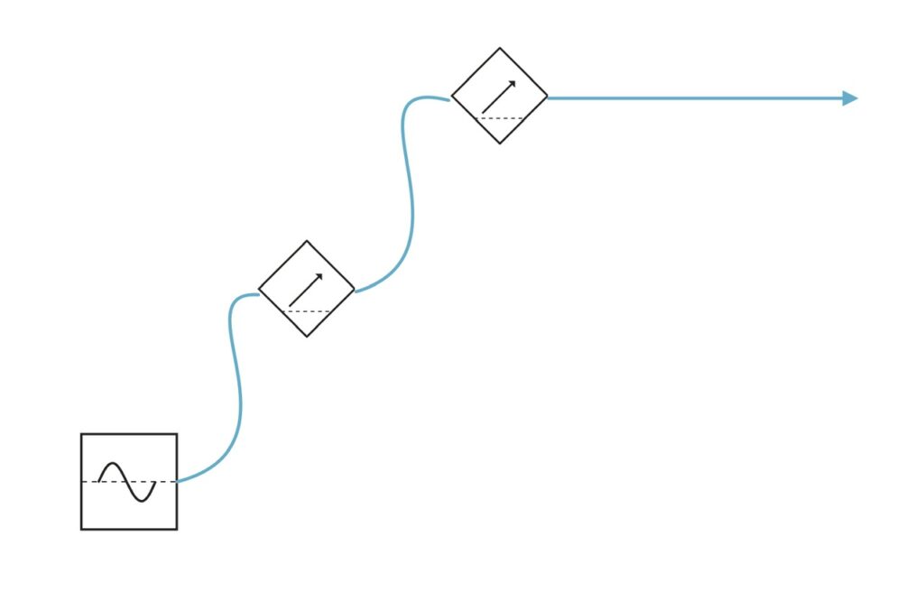
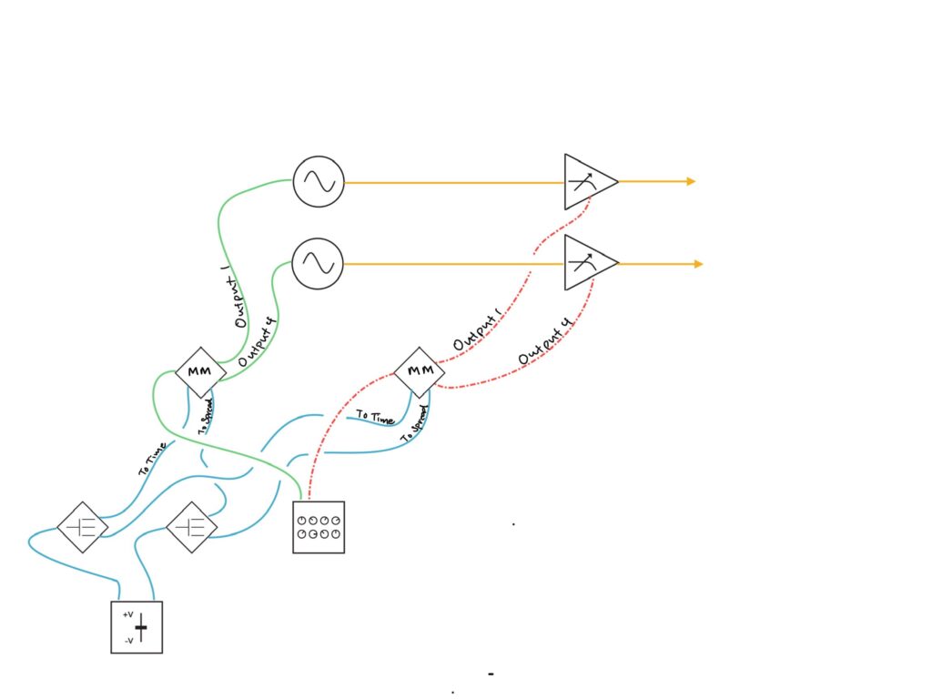
To start, I copied a x2 clock from Tempi to both Multimod Tempo inputs, with a second /16 clock to both Reset inputs. This ensured that the clocks of both units would always be in sync. I then patched René’s X CV channel to the first Multimod input, and the X Gate output to the second Multimod input. The Init setting on both Multimods were simple: Phase at full CCW, Spread at Noon, with the Spread CV attenuverter at full CW, and Time at full CCW. With these settings, things worked just as they should: a single CV and gate sequence from all eight outputs happening at precisely the same time. So far, so good. I then patched the Lemon fader CV outputs to the CV Bus, and then to both the Time and Spread CV inputs on both Multimods.1 A single CV source should (again, theoretically) modulate both units identically such that as the CV sequence speeds up (or slows down), the gate sequence simultaneously does the same, and corresponding outputs on each Multimod should remain in sync.

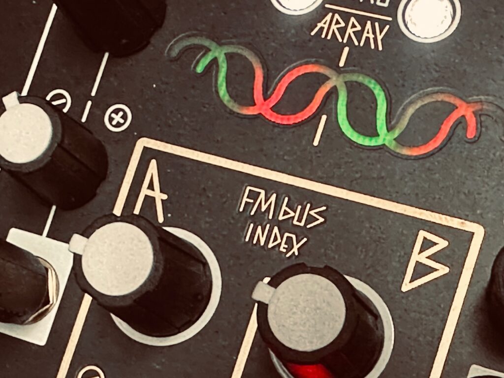
For the oscillators I chose the Spectraphon.2 The first Multimod output one was patched to Oscillator A, with Output four patched to Oscillator B. The mixed outputs of each side of Spectraphon were then patched to QMMG inputs one and two. Outputs one and four of the second Multimod were patched to QMMG’s CV inputs, with both QMMG channels in LPG mode (though it sounded cool in LPF mode too). With identical modulation going to both the Time and Spread CV inputs of both Multimods at the same time, the CV and Gate sequence outputs should (theoretically) also be in sync with changes. The CV sequence from output one on the first Multimod should match the gate sequence from output one on the second Multimod. Ditto with the other outputs.

To be honest, I’m not sure if the patch worked like it should have in theory. What I mean to say is that the result is ultra-cool whether theory was borne out in practice or not. Things sound correct with the resulting sequence from Multimods output four, the output that is affected least by changes to Time and Spread. But I can’t really tell if the pitch and gate sequences from Multimods output one, the output affected most by changes to Time and Spread, is synced in the same way. The sequence is moving pretty fast. Hearing individual triggers can be tough at super high speeds, especially when slamming triggers into vactrols, like those in QMMG. Not only is there inherent bleed, but the fall response is such that you can’t always hear individually triggered notes if they’re in quick succession. DXG would likely have been a better candidate for testing the precision of the altered sequence because each trigger is annunciated clearly in a way that isn’t possible with vactrols. That said, I’m a huge fan of vactrol bleed. It can be a beautiful effect when used with intention, and although I wasn’t looking for any particular sound with this patch, vactrol bleed certainly showed off its character in this test recording.

This diagram is missing the clock and reset to the Multimods.

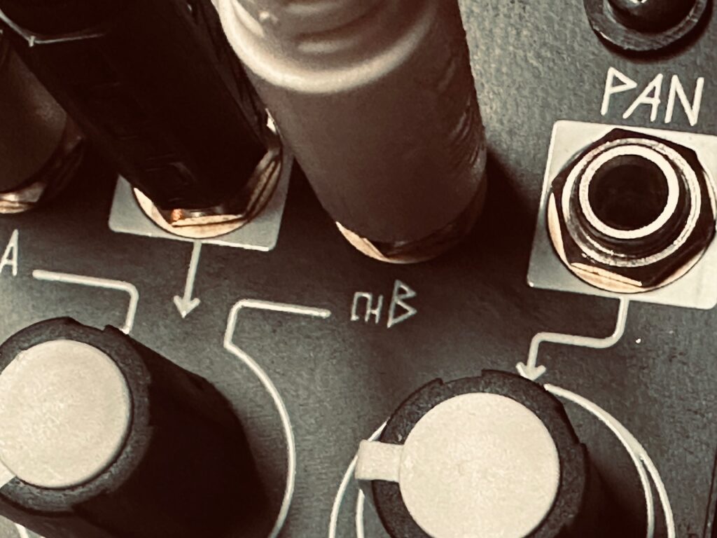
The QMMG outputs were sent to X-Pan, with the Channel four sequence mixed in the middle, while the Channel one sequence was slowly panned left to right and back again through the stereo field by a cycling Maths triangle function. The stereo output of X-Pan was sent to Mimeophon for some finishing with beautiful repeats and Halo.

Modules Used:
Tempi
René Mk2
Multimod
Maths
Spectraphon
QMMG
X-Pan
Mimeophon
Wogglebug

Outboard Gear Used:
Noisy Fruits Lab Lemon

Improvised and recorded in one take on iPad in AUM via the Expert Sleepers ES-9.

  1. As mentioned previously, the same thing can be accomplished with any offset generator like Maths or ChnSvr. ↩︎
  2. Seriously, Make Noise: Spectraphon is awesome, and I’ve never even explored it beyond SAO mode with the default Spectra. ↩︎

Jamuary 2528

Long day at work so this will be a quick and dirty patch notes….

The Make Noise system has my back again.

QPAS pinging away. Sequenced and pinged by René. Smile Pass and Bandpass outputs both sent to X-Pan and crossfaded, although I don’t know there’s much difference between them in the output. Spectraphon supplied both ring modulated and FM tones. For FM tones, Spectraphon A is on left, Spectraphon B on right. They are tuned an octave apart. Both mixes enveloped by a Fall modulated Maths functions in DXG.

Both QPAS and Spectraphon had every CV input modulated by…something. Wogglebug, René, Maths, Tempi, Maths Functions, the OR and SUM outputs on Maths, and just about anything else I could find.

Everything mixed in DXG and sent to Mimeophon for some delay and a decent amount of Halo. Had a little too much fun using the 0-Coast Slope output to modulate Mimeophon’s uTime CV input.

Kick was created by the 0-Coast. A steady clock from Tempi triggered the Contour on the 0-Coast. The Contour output was attenuated and sent to the v/oct input to give the kick some punch. The kick is dry in the mix.

Modules Used:
René Mk2
Tempi
Spectraphon
ModDemix
Function
QPAS
Maths
Wogglebug
X-Pan
Mimeophon
0-Coast

Improvised and recorded in one take on iPad in AUM via the Expert Sleepers ES-9.

Stochastic Waves

I’ve used all kinds of slow modulation sources in my patches. Wave simulators, chaos, and slow, free-running LFOs are all staples in my modular practice, and I’ve used all of them as the engine that drives an entire patch. But one thing I’ve never tried in a lead role in a patch is good, old fashioned random modulation. Sure, I’ve used sample and hold or smooth random generators like the Frap Tools Sapél, Mutable Instruments Marbles, or Make Noise Wogglebug for specific tasks within a patch, but outside of Marbles > Rings-type patches, I’ve never based a patch on staochastic movement before.

Random is, well, random, and it’s hard to be intentional when you can’t really expect what’s going to happen next. In some circumstances, that unpredictability is perfect. In other cases, it just makes a really big mess. There are certainly ways to corral in a random signal to fit within particular parameters to allow for more predictability. That’s the basis of stochastics. Sapél has a range probability knob which directs it to choose output values predominantly from a particular range. Marbles has a switch for voltage ranges. Wogglebug similarly has a mechanism for more or less drastic changes. You can even hone random voltage in on your own with a little offset and attenuation. But it’s still random, and even if completely random might work for certain facets of a patch, using it as the main driver becomes difficult while still remaining musical.1 But I was determined to make it work, and I had just the module to help.

The Addac506 Stochastic Function Generator is a powerhouse modulation source made up of four function generators, and most of the bells a whistles one could want. Need cycling envelopes? Check. Slew limiter? Check. One shot envelopes? Check. Audio rate to very slow? Check. EOR and EOC trigger outputs. Check. Offset and attenuation to get your generated functions in the exact range you need it? Check? Some comparator action for related modulation? Check? And this checklist of features goes on and on. But the killer app of the Stochastic Function Generator is its ability to set a very precise range for both Rise and Fall times. This ability allows for some very compelling modulation that changes every cycle, but, particularly when using very slow modulation, does so organically in a way that seems transparent. It can be set to no random generation (standard envelopes), a very wide range with wildly changing Rise and Fall times, or a very narrow range where changes are subtle, and each of these can be done in three modes, slow, medium, or fast (per generator). The Addac506 is a very powerful module with a compelling feature set that can drive entire patches.

I had set out to make another E370 patch using slow modulation to fade the four wavetable oscillators in and out to create a cloud of a chord that is constantly shifting, yet still always the same. I’d been using slow moving bipolar signals for this purpose on several patches of late, but I wanted to try something a little different this time around. I’ve used chaotic systems, and I’d used both free running and synced LFOs, but I’d had problems using cycling unipolar functions in the past because no voice is ever truly out for very long. It’s a constant chord where each note changes volume, but is almost always audible. Mystery, drama, and tension are minimized; each note like a yo-yo rather than a graceful flow in and out and back in again. But the Addac506 is a little different. Unlike most function generators, with the Stochastic Function Generator you can tailor the outputs to any range you want. Those functions needn’t be unipolar, nor with wide ranging levels, and the ability to offset and attenuate signals allows one to shape your function to suit your destination without issue, and it’s this ability to perfectly condition CV before ever leaving the module that enabled me to use it in this slow fading movement I was looking for.

Setting the stochastic functions on the Addac506 is simple: set minimum and maximum Rise and Fall times, and call it a day. At the instantiation of every cycle both Rise and Fall will receive a random value between those set minimum and maximum times, and that stochastically determined envelope will come out. Flick the cycling switch and every cycle is something different. And the Addac506 gives us that, times four. It should be noted that this behavior can be replicated in any function generator that has both End Of Rise and End Of Cycle gate/trigger outputs, plus CV inputs to control the rise and fall times independently. You’ll need to add in a sample and hold or random voltage generator, plus a module for offset and attenuation to define the range of random. All this times four is a lot of patching, and a lot of modules. The Addac506 does it all seamlessly under the panel.

At first I was a little confused. Although I hadn’t initially set any offset, the output was still silent until the voltage as somewhere between 1-2 volts.2 I had anticipated needing to use negative offset to create some space between the fading out of one wave and when it will become audible again, but instead found myself using positive offset to get the flow I was after. Fortunately the flexibility of the Addac506 allowed for quick and easy adjustments to put each wave in the right zone. I added a fair amount of positive offset to the bass note of the chord so that it was always audible, while still having level changes to keep it moving. The other three oscillators used a very slight positive offset. Combining their need to get to somewhere between one and two volts before becoming audible, with the very slow nature of these ever-evolving functions determined the use of positive offset. Up to 40% of their positive range was already inaudible. Giving the functions a bit of a voltage floor rise was in order, lest far too much silence ensue.

Having already decided on my four oscillators for this chord soup, the quad wavetable oscillators of the Synthesis Technology E370, and having had the level control roughly framed out, it was time to look at modulating the wavetables to create movement within each note. The pitch of each oscillator would remain static, and to accompany the change in level, a change in timbre is natural (especially with a morphing wavetable oscillator). Having already used up the outputs of the Addac506, I looked to a familiar module, and one right next to the Stochastic Function Generator, the Addac508 Swell Physics.

Although Swell Physics is definitionally a chaos-based system, and not a random one, the uneven flow up and down of each output was perfect for the job. The bass note oscillator received modulation only on its Detune CV input, while the other three oscillators received both Wave and Detune modulation, the former from Swell Physics and the latter three free running sine wave LFOs from Batumi II. The triangle wave LFOs from Batumi II were used to pan these same three signals slowly through the stereo field with the ST Modular Sum Mix & Pan, while the bass note was planted firmly in the center. Once mixed down to stereo, the four oscillator cloud went to the AI Synthesis 018 Stereo Matrix Mixer.

Once in the matrix mixer it was time to smooth out some of the rough edges with the Holocene Electronics Non-Linear Memory Machine, a favorite of mine since it went in the rack. As a non-clockable delay I found it a wonderful tool for long, drawn out ambient delays, especially with how it can smear repeats into an almost reverb-like sound. Although I tend to pretty heavily modulate the NLMM, I chose to go with no modulation in this patch, with smearing at about 12 o’clock on the knob, and feedback at around 11 o’clock. The NLMM was mixed with the dry signal in the matrix mixer at about a 50:50 ratio, and perhaps even favoring a bit more delay than dry signal.

This mixed signal was sent to both the output mixer and The Dradds for some broken tape machine treatment. Both sides, left and right, or light and dark as it exists in my case, were set to Tape mode at an octave up, with each side behaving slightly differently. The left side tends to randomly switch between forward and backwards playback at double-speed, while the right side randomly switches both direction and speed, although both sides were lightly modulated and sometimes change temporarily. Although I’ve always been enamored by the Dradd(s), it wasn’t until I really started to learn it have my results been what I was always hoping for. Since I sat down to really understand the Dradd(s), my patching has had an opportunity to be more intentional, with my results more satisfying and effective. Plus, having dual Dradds for a stereo field really maximizes the movement and variation it creates.

The Dradds, good and evil.

A heaping portion of distortion, courtesy of the Bizarre Jezabel Mimosa, was also used towards the end of the patch, which created occasional blips and stutters, and a sense of heavy drama. It was only used on the chord cloud and the Dradds, and even then I chose to keep a fair bit of the original dry signal in the mix. I really like the resulting sound, but something is happening that I don’t quite understand. As distortion was introduced into the mix, I did not lower the dry signal. I would have expected the volume would rise, yet it didn’t. The volume got lower, even once the dry and wet distortion signals were nearing full volume in the matrix mixer. It wasn’t until I started to lower the dry signal (the chord, its delayed signal from the NLMM, and the Dradds) that the overall volume started to become louder. My guess is there is some form of phase cancellation happening, although I don’t really know what phenomenon might explain it. You can hear it starting at about the 10 minute mark, with me starting to lower the dry level at about the 11:22 mark, which corresponded in a total output level rise. Curious, that.

Although I was quite happy with my shifting chord after a whole lot of tinkering with envelopes and CV input attenuators, I knew something was missing. I had blips of granular synthesis to break things up, but it needed more. I was hesitant to use SD Multisample as I’ve done a lot of that, but wanted something in a similar vein. Reaching back to one of my very first patches, an attempt at creating a wind chime-like sound and pattern, I decided to add in a randomly created, toy piano sound (or baby R2-D2 sounds as my oldest relayed ). I really enjoyed making that patch when I did it the first time around. It was the first patching technique I’d ever figured out on my own, and a sense of nostalgia pushed me over the edge, even if only to see if I could remember how to replicate it.

This part of the patch started at the Stochastic Function Generator’s “Average” output. This output was patched to the input of the Joranalogue Compare 2. When the Average out from the Addac506 was inside the comparator window, it spat out a gate to the cycling input on a Frap Tools Falistri. While the function was cycling, the End Of Cycle gate triggered Sapel and Quantermain. Sapel sent a value from the N2 output to both Quantermain, in order to send quantized pitch CV, and the Decay CV input of Falistri that would change the envelope length with each note. The VCO changed pitch, and the cycling envelope opened the VCA, each note with a different pitch and length. The sound went from the first VCA to the output mixer, as well as a second VCA which panned the signal to two separate delays, which were then mixed and sent to the output mixer to be mixed with the dry signal and the rest of the patch.

Although the method I ultimately used in this patch is very different than the first time around, the results are similar. The sounds are much higher in pitch, much faster, and much shorter than my original version, but the theory behind creating the sounds was the same, even if I took a different route to get there.3 I wanted short, uneven bursts, and I got them. It’s quite often these days that I realize there are many routes to the same end. Overall, this part of the patch played a very minor role, but an important one. After several listens, I’d probably integrate this part differently were I to do it again. I’d definitely have it more forward for most of the mix rather than hanging around the background. It seems to get lost sometimes, when it should be more prominent. I would also not mess up a patch connection with my second delay, the Qu-Bit Electronix Nautilus, where I plugged into the Right input, and not the left, which, with the feedback pattern chosen, put virtually all of the delay signal from Nautilus on only the Left side. Some might not even notice, but it bothers the shit out of me.

The last part of this patch is the periodic “bubble burst” with accompanying echoes (courtesy of the Xaoc Devices Sarajewo). I stole this idea straight from one of my favorite patches on the Make Noise channel. It’s a simple sound that is both unobtrusive, and only very periodic. The sound was created by pinging (ringing?) CUNSA, which also had its frequency modulated by the highly attenuated HP output of the same filter (another trick I stole from Make Noise – Thanks, Walker!). It was triggered by using a Stackcable to combine three separate gate outputs from the Stochastic Function Generator. These long functions output only very periodic gates at a random interval, so there’s no overcrowding. It also helped provide a sense of scale and depth of the musical space.

Everything ended with a round trip through the Walrus Audio Slöer, which is quickly becoming my favorite reverb. Although I’ve tended towards one of the pitch shifting algorithms, I ultimately decided on using the Dream algorithm, though the Rain algorithm also sounded nice.

I really enjoyed this patch, even if there are a few things I would definitely change. It was both challenging and highly rewarding. It offers answers to some questions, but also to more questions to explore in a future patch.

Modules Used:
Addac506 Stochastic Function Generator
Addac508 Swell Physics
Synthesis Technology E370
ST Modular Sum Mix & Pan
Frap Tool CUNSA
Frap Tools Falistri x2
Frap Tools Sapél
Joranalogue Compare 2
Befaco/DivKid Stereo Strip
Calsynth uO_C (Quantermain)
Bizarre Jezabel Mimosa
Knob Farm Hyrlo
Venus Instruments Veno-Echo
Qu-Bit Electronix Nautilus
Xaoc Devices Batumi II
Xaoc Devices Samara II
Xaoc Devices Sarajewo
CuteLab Missed Opportunities
Holocene Electronics Non-Linear Memory Machine
AI Synthesis 018 Stereo Matrix Mixer
Knob Farm Ferry

Outboard Gear Used:
Walrus Audio Slöer

  1. Although what is or isn’t “musical” is certainly subject to wide interpretation, I think we can still make useful generalizations, while drawing lines between something most would call musical, with yet other examples most would call sound(s) or noise. ↩︎
  2. I’m not sure, but I suspect that the VCA/mixer I was using to process the audio has a logarithmic response, delaying its response with slow(er) signals. The manual doesn’t illuminate the VCA topography, unfortunately. ↩︎
  3. After looking at a patch diagram of the original patch, the methods used between these two patches was quite different, even if it started similarly. It’s nice to know that there is generally more than one way to accomplish some patching goal. ↩︎

Quick Tip #1: Fine Tuning Modulation

Modulation is what makes modular synthesis a compelling medium. Without control voltage, boredom ensues. But sometimes finding just the right amount of modulation is often tedious, if not difficult. Too much and chaos ensues. Too little and you might as well not use any at all. To help find that sweet spot, try fine tuning your modulation.

It’s simple: Use two VCAs in series. When you route a control signal to a VCA, you can attenuate it to help find the course range. But if you route the output of an attenuated VCA into a second VCA, you will now have a full knob’s worth of control on a smaller portion of the original signal, maximizing your resolution and more easily allowing you to find the perfect amount of modulation.

This technique works especially well when mixing with an offset voltage with the fine tuned CV because you can narrow your CV to a very specific range.

0:00
0:00